


Project Management
Leads all phases of construction—planning, team coordination, quality control, budgeting, and communication—to ensure the project is completed safely, on time, and within budget.

Estimation
Calculates project costs by analyzing plans and specs to determine material, labor, and equipment needs. Delivers accurate bids essential for budgeting and profitability.
Engineering Plans
Designs and analyzes foundation systems using soil data and load requirements to ensure structural stability and safety. Oversees construction and testing of foundations.

Claims support
Provides expert assessment of foundation damage, including cause, extent, and repair needs. Supplies objective reports to support or challenge insurance or legal claims.

Expert witness
Offers unbiased, expert testimony in legal cases involving foundation design, performance, or failure, based on specialized knowledge and experience.

Post project analysis
Assesses foundation performance after completion, investigates issues, monitors stability, and provides reports with recommendations for any necessary corrective actions.
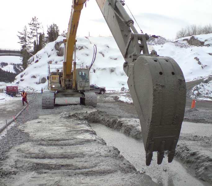
Piles are structural elements of a deep foundation system that are installed to transfer loads from a structure through weak or compressible surface soils to stronger, more stable soil or rock layers at depth. They are used when shallow foundations, such as spread footings or mats, are not feasible due to geotechnical constraints or structural demands.
The primary purpose of a pile is to develop load-carrying capacity through end-bearing (transferring loads directly onto a competent stratum) and/or skin friction (transferring loads via frictional resistance along the shaft of the pile). Piles are critical for resisting axial loads (compression and tension) as well as lateral loads, depending on the design criteria.
Common Reasons for Using Piles
Engineers may specify pile foundations in the following scenarios:
- Weak or Compressible Surface Soils: Where the upper strata cannot safely support structural loads (e.g., soft clay, peat, loose fill).
- High or Concentrated Loads: Tall or heavily loaded structures often require deep foundations to distribute loads adequately.
- Expansive or Collapsible Soils: Such as certain clays or loess, where shrink-swell behavior or sudden collapse can compromise shallow foundations.
- High Water Table or Liquefaction Risk: Deep foundations bypass saturated, unstable layers that may liquefy during seismic events.
- Lateral Load Resistance: For structures like bridges, retaining walls, or marine structures where lateral stability is required.
- Site Constraints: Urban environments or sloped sites where there is limited space for large footing excavations or where adjacent structures impose load or excavation restrictions.
- Scour Resistance in Water Bodies: Piles are often used in riverbeds, ocean floors, or flood-prone areas to resist erosion and scour.
Types of Piles and Materials
Piles are generally classified based on material, installation method, and structural function:
By Material:
- Concrete Piles: Precast or cast-in-situ, reinforced or prestressed. Common in infrastructure and building foundations.
- Steel Piles: H-piles or pipe piles, often used where high strength and deep penetration are required.
- Timber Piles: Cost-effective for light structures and temporary works; commonly used in low-rise waterfront infrastructure.
- Composite Piles: A combination of materials (e.g., concrete-filled steel pipes) to optimize structural and geotechnical performance.
By Installation Method:
- Driven Piles: Hammered or vibrated into the ground; provide good quality control through driving resistance.
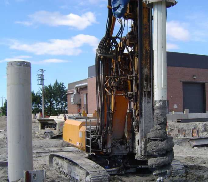
- Bored (Drilled) Piles / Caissons: Installed by drilling a shaft and filling it with concrete; ideal in urban or noise-sensitive areas.
- Screw Piles (Helical Piers): Mechanically twisted into the ground; suitable for light to moderate loads and fast installation.
- Displacement Piles: Installed without removing soil, increasing lateral stress in surrounding soil and improving capacity.
- Micropiles: Small-diameter, high-capacity piles drilled and grouted under low headroom or restrictive access conditions.
The selection of pile type and installation technique is governed by geotechnical investigation data, structural loading, environmental constraints, vibration or noise limits, and economic considerations.
Iconic Structures Supported by Pile Foundations
Many world-renowned structures rely on pile foundations due to their challenging site conditions or immense structural demands:
- The Burj Khalifa (Dubai, UAE): The world’s tallest building rests on a deep foundation system comprising over 190 reinforced concrete bored piles, each 1.5 meters in diameter and extending over 50 meters deep.
- The Millau Viaduct (France): This iconic cable-stayed bridge, the tallest in the world, is supported by massive deep foundations, including large-diameter drilled shafts socketed into bedrock.
- The Venetian Hotel (Las Vegas, USA): Built on soft, compressible desert soil, it is supported by over 500 steel pipe piles to ensure stability under the massive load of the structure.
- San Francisco–Oakland Bay Bridge (USA): Parts of the bridge are supported by steel piles driven more than 90 meters below the seabed to address seismic risk and unstable sediments.
- The Panama Canal Locks Expansion: The new locks are founded on driven and drilled piles due to variable soil conditions and high operational loads.
Conclusion
Pile foundations are indispensable in modern construction where ground conditions or structural demands exceed the capacity of conventional shallow foundations. By transferring loads to deeper, more stable strata, piles ensure the safety, serviceability, and durability of critical infrastructure. Their design and implementation require careful coordination between geotechnical, structural, and construction disciplines to address both engineering performance and constructability. As urbanization and infrastructure development continue to push the limits of design and site adaptability, pile systems remain at the core of reliable and resilient foundation engineering.
underlying soils and site constraints and property lines. There are several different types that exist, and their installations also vary along with sometimes their materials. Piles can be made from wood, steel, concrete and a composite of both steel and concrete. They can be driven into the ground, drilled, screwed, and pushed hydraulically. The selection of the material and installation varies often due to site conditions and underlying soil stratums.
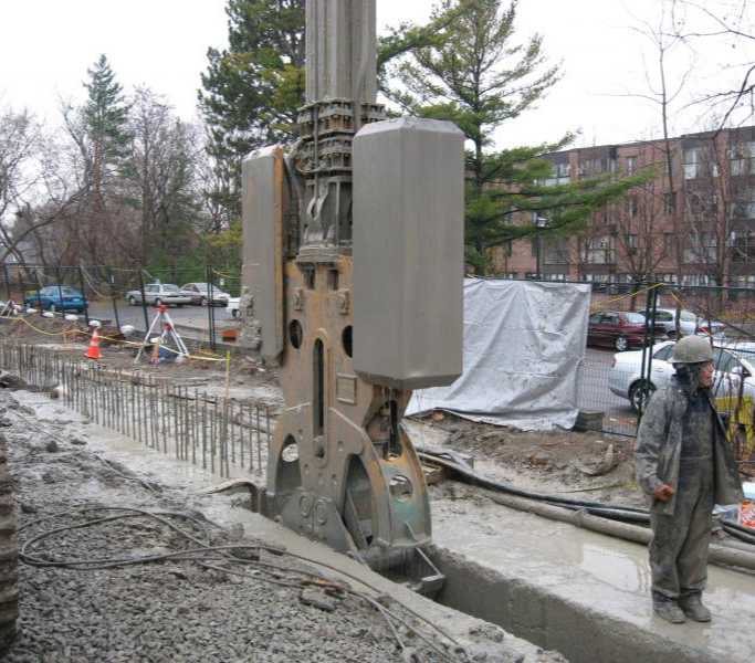
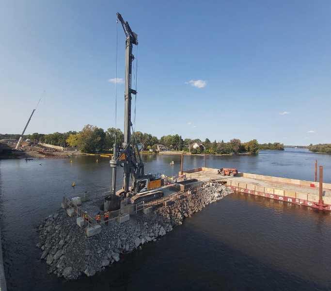
Caissons are deep foundation elements that are typically constructed by drilling a large-diameter shaft into the ground and then filling it with reinforced concrete. They are often referred to as drilled shafts or bored piles, although in technical practice, caissons usually imply larger diameters and a higher degree of structural complexity.
Unlike driven piles, which are installed by impact or vibration, caissons are formed by excavation and allow for precise placement and control, making them well-suited for urban or sensitive environments where vibration must be minimized.
Key Characteristics of Caissons
- Large Diameter: While there is no strict diameter threshold, caissons are usually much larger than standard piles, often exceeding 1 meter and, in major infrastructure projects, can reach 3 meters or more in diameter.
- Drilled and Cast-in-Place: Caissons are not pre-manufactured like many piles. They are constructed in situ by drilling to the required depth, cleaning the borehole, placing reinforcement cages, and pouring concrete.
- Socketed into Rock: A defining feature of caissons is the presence of a rock socket, where the shaft is drilled into competent bedrock or very stiff soil. This rock-socketing enables the caisson to develop high end-bearing and side friction resistance, making it ideal for high axial and lateral loads.
- High Load Capacity: Due to their large cross-sectional area and deep embedment, caissons provide superior axial (compression and tension) and lateral load resistance, and are often used for bridge piers, towers, wind turbines, and other heavy infrastructure.
- Heavily Reinforced: Caissons are almost always constructed with steel reinforcement, both longitudinal and transverse, to resist bending, shear, and seismic forces.
Differences Between Caissons and Piles
Feature | Caissons | Piles |
Installation Method | Drilled, excavated, then cast in place | Driven, drilled, screwed, or jacked |
Diameter | Generally large (1–3+ meters) | Smaller (typically <1 meter) |
Material | Reinforced concrete only | Concrete, steel, timber, or composite |
Load Capacity | Very high axial and lateral resistance | Varies depending on type and installation |
End Condition | Often socketed into bedrock | May be friction piles, end-bearing, or both |
Construction Control | Allows full inspection before concreting | Less visible control—must rely on driving logs |
Vibration / Noise | Minimal (ideal in urban zones) | Can be high (especially for driven piles) |
Common Use | Bridges, towers, heavy infrastructure | Buildings, retaining walls, lighter structures |
Conclusion
While both caissons and piles serve the purpose of transferring structural loads to deeper, more stable layers, caissons are distinguished by their larger size, construction technique, and load-carrying potential. Their ability to be socketed into rock and to resist significant lateral forces makes them a preferred choice for critical and high-load structures. However, caissons are generally more expensive and time-consuming to construct, requiring specialized equipment and site conditions that accommodate large-scale drilling and concreting operations.
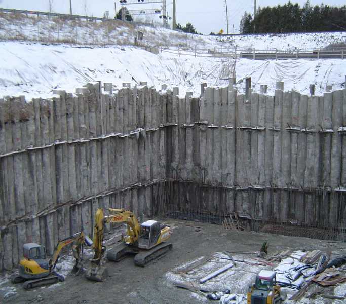
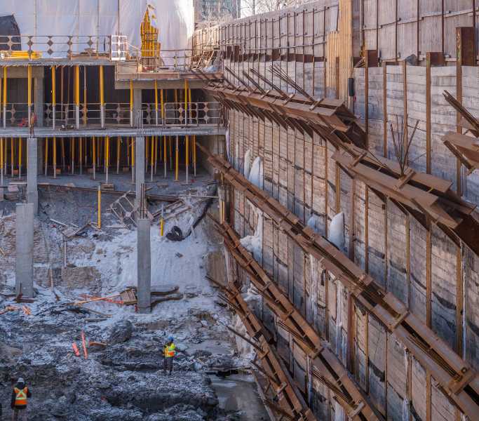
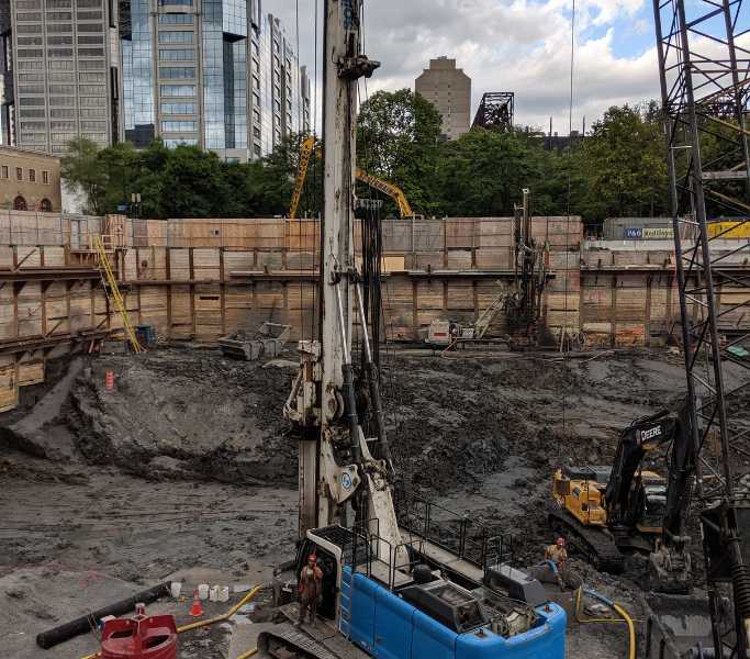
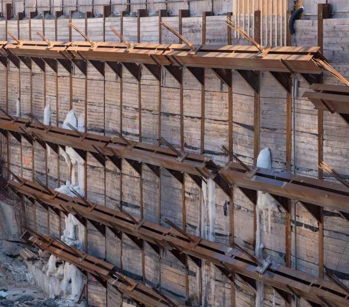
Berlin walls, also known as soldier pile and lagging walls, are among the most commonly used temporary or semi-permanent retaining systems in urban excavation projects. Their widespread popularity stems from their versatility, cost-effectiveness, and adaptability to various site conditions.
Advantages of Soldier Pile and Lagging Systems
- Versatility in Installation Methods
Soldier piles can be either driven or drilled and socketed, making them suitable for a broad range of soil profiles, including those containing cobbles, boulders, or mixed fill materials that would typically obstruct the installation of other systems such as sheet piles. This flexibility allows engineers to adapt the method to both open and congested urban environments. - Cost Efficiency
Soldier pile and lagging walls are typically more economical than other earth retention systems due to:- Reduced material costs (e.g., using timber lagging instead of steel panels).
- Minimal excavation support hardware.
- Simpler and faster installation processes.
- Lower mobilization costs, particularly when using readily available drilling rigs.
- Ease and Speed of Construction
The system is relatively simple to design and install, requiring only the placement of piles at regular intervals followed by the sequential installation of lagging boards as excavation progresses. This makes it ideal for tight construction schedules or emergency shoring needs. - Minimal Footprint
Soldier pile walls require less horizontal space compared to sloped cuts or some soil nail systems, making them particularly attractive in urban settings, close to property lines or adjacent structures.
Lagging Materials and Cost Considerations
The use of timber lagging between soldier piles provides a significant cost advantage over systems that rely on precast concrete or steel sheeting. While wood is not permanent and may deteriorate over time, it is sufficient for temporary applications and easy to replace or reinforce when needed.
Limitations and Considerations
Despite their popularity, soldier pile and lagging systems are not suitable in all conditions:
- Poor performance in high groundwater environments
These systems are not watertight, and significant groundwater can lead to lagging washout, soil loss, or hydraulic pressure buildup behind the wall. In such cases, additional dewatering or alternative systems (e.g., secant piles or slurry walls) may be required. - Limited structural stiffness
Soldier pile walls are inherently flexible, especially in taller cuts or in the absence of anchors or struts. This flexibility can lead to excessive deflections, which pose a risk in areas with sensitive adjacent structures, such as roads, sidewalks, utilities, or nearby foundations. - Not ideal for permanent walls without upgrades
While they are often used in temporary excavation support, turning a soldier pile and lagging wall into a permanent retaining structure typically requires corrosion protection, permanent lagging (e.g., shotcrete or concrete panels), and waterproofing, increasing overall cost and complexity.
Conclusion
Soldier pile and lagging walls (Berlin walls) are popular due to their constructability, flexibility, and cost-effectiveness in a wide variety of soil and site conditions. They provide an efficient and reliable solution for temporary excavations and are a preferred choice for many urban infrastructure and building projects. However, engineers must remain cautious of their limitations in groundwater control and deflection management, especially near critical or sensitive infrastructure. Proper geotechnical investigation and wall design are essential to ensure performance and safety.
1. Soldier Pile and Lagging Walls (Berlin Walls)
Overview:
Soldier pile and lagging systems consist of vertical steel H-piles installed at regular intervals, with horizontal lagging elements (typically timber or precast panels) placed between the piles as excavation progresses.
Advantages:
- Highly versatile (can be drilled or driven).
- Economical and fast to construct.
- Minimal impact on adjacent structures during installation.
- Ideal for temporary works and urban environments.
Limitations:
- Not watertight.
- Flexible system—large deflections may occur without anchors.
- Poor suitability in high groundwater or loose, cohesionless soils.
- Requires additional detailing for permanent use (e.g., corrosion protection).
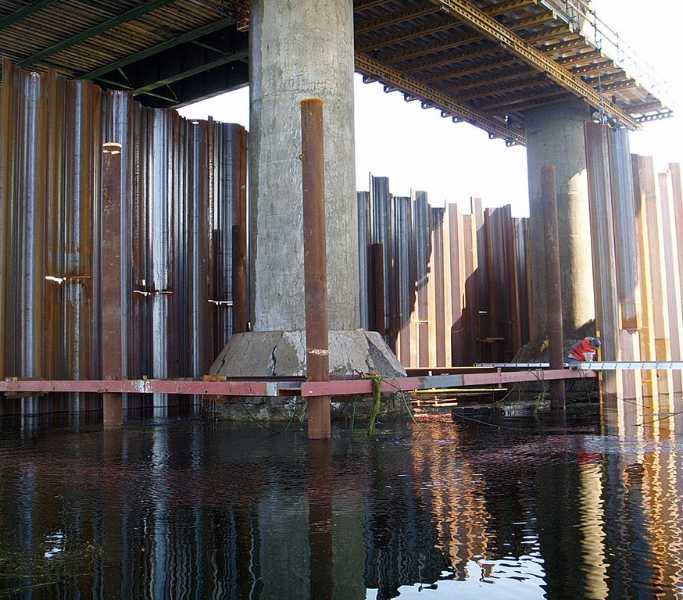
2. Sheet Pile Walls
Overview:
Sheet piles are interlocking steel sections driven into the ground to form a continuous vertical wall. They are often used in marine environments or where water cutoff is required.
Advantages:
- Provides good water tightness.
- Fast to install in soft soils.
- Suitable for deep excavations and permanent structures.
Limitations:
- Difficult to install in dense, gravelly, or boulder-laden soils.
- Noisy and vibration-prone installation (can affect nearby structures).
- Can be costly in small-scale projects or where cut-off isn't required.
- Limited stiffness compared to reinforced walls.
3. Secant Pile Walls
Overview:
Secant pile walls consist of overlapping concrete piles (alternating soft and hard piles), forming a continuous wall. Reinforced piles provide structural support; unreinforced piles offer water cutoff.
Advantages:
- Excellent groundwater control (near watertight).
- High stiffness—minimal deflections.
- Can be constructed in a wide range of soils, including bouldery or urban fill.
- Suitable for deep and permanent excavations.
Limitations:
- High cost and construction complexity.
- Requires precise alignment and specialized equipment.
- Slower installation compared to soldier piles.
4. Diaphragm Walls (Slurry Walls)
Overview:
Diaphragm walls are constructed by excavating a trench in slurry (usually bentonite), then filling it with reinforced concrete. These walls are continuous and typically very thick.
Advantages:
- High structural capacity and stiffness.
- Excellent for deep excavations and permanent basements.
- Effective groundwater barrier.
- Minimal vibration and noise during installation.
Limitations:
- Very expensive and equipment-intensive.
- Long construction time.
- Requires strict quality control (slurry management, trench stability).
5. Soil Nail Walls
Overview:
Soil nails are passive reinforcement elements installed in the soil and combined with a facing system (e.g., shotcrete) to stabilize excavated slopes.
Advantages:
- Cost-effective for staged excavations in cohesive soils.
- Minimal ground disturbance.
- Flexible for irregular geometries and top-down construction.
Limitations:
- Not suitable for loose or granular soils without cohesion.
- Limited applicability in high water table conditions.
- May require temporary support during construction until sufficient nails are installed.
6. Tangent Pile Walls
Overview:
Tangent piles are constructed similarly to secant piles but do not overlap. This creates a continuous but non-waterproof wall of adjacent concrete piles.
Advantages:
- Good structural capacity.
- Simpler construction than secant walls.
- Suitable for semi-permanent uses or where groundwater control is not critical.
Limitations:
- No groundwater cutoff.
- Requires careful alignment to avoid gaps.
- Higher cost than soldier pile systems.
Summary Table – Retaining System Comparison
System | Cost | Stiffness | Water Tightness | Noise/Vibration | Constructability | Use Case |
Soldier Pile & Lagging | Low | Low–Medium | Poor | Low (if drilled) | Simple, fast | Temporary works, urban sites |
Sheet Piles | Medium | Medium | Moderate–Good | High | Fast in soft soils | Marine, flood protection, water control |
Secant Pile Walls | High | High | Excellent | Low | Complex, precise | Deep, watertight, permanent applications |
Diaphragm Walls | Very High | Very High | Excellent | Very Low | Equipment intensive | Large-scale basements, high-rise cores |
Soil Nail Walls | Low–Medium | Medium | Poor | Very Low | Adaptable, staged | Cut slopes, temporary shoring |
Tangent Pile Walls | Medium–High | High | Poor | Low | Less complex than secants | Semi-permanent walls, dry conditions |
Conclusion
The choice of retaining wall system depends on multiple factors, including soil conditions, groundwater table, structural requirements, space limitations, budget, and construction timeline. Soldier pile and lagging walls remain a top choice due to their economy, simplicity, and adaptability, especially in temporary excavations in urban environments. However, more robust or watertight systems such as secant piles or diaphragm walls are essential where deep excavations, minimal movement, or groundwater control are critical.
A comprehensive geotechnical investigation, paired with structural modeling and a clear understanding of project constraints, is essential for selecting the optimal shoring system.
While sheet piles are a cost-effective and commonly used shoring system for temporary and permanent excavations, they are not always a viable solution, especially in challenging ground conditions. In such cases, secant pile walls, although more expensive, offer technical advantages that can justify their selection.
Limitations of Sheet Piles
Sheet piles are typically installed by driving or vibrating interlocking steel sheets into the ground. While fast and economical in soft or medium soils, their effectiveness is limited in certain conditions:
- Obstruction by Dense or Hard Soil Layers:
In the presence of dense clays, glacial tills, gravelly soils, cobbles, or bedrock, sheet piles often refuse to penetrate to the required depth. This can result in incomplete embedment, structural instability, or inadequate water control. - Damage During Driving:
Sheet piles are susceptible to tearing or deformation when encountering obstructions. This compromises both the integrity of the wall and its watertightness. - Vibration Issues:
The driving process can generate significant vibration and noise, making sheet piles unsuitable in sensitive urban environments, near old foundations, utilities, or vibration-sensitive equipment.
Advantages of Secant Pile Walls
Secant pile walls are constructed using overlapping drilled concrete piles, often alternating between primary (unreinforced) and secondary (reinforced) piles. Their drilled construction method and continuous configuration offer several key advantages:
- Effective in Difficult Soil Conditions:
The drilling process allows secant piles to penetrate dense soils, glacial deposits, fill with debris, and soft rock layers, where sheet piles would otherwise fail or deform. - Watertight Retention:
Properly designed secant walls provide an almost continuous barrier, offering excellent control of groundwater. This is especially valuable in excavations near basements, tunnels, or contaminated soils. - Low Vibration Construction:
Drilling produces minimal vibrations, making secant walls ideal in urban or vibration-sensitive areas where traditional pile driving is restricted. - Customizable Geometry:
Secant walls can be curved or shaped more flexibly than interlocking sheet piles, allowing greater design freedom around complex site layouts.
Conclusion
Although secant pile walls involve higher upfront costs due to their material requirements, drilling precision, and longer construction time, they offer superior performance in geotechnically complex environments where sheet piles are not feasible.
In projects involving:
- Very dense soils or rock layers,
- Strict groundwater control requirements, or
- Sensitive urban environments,
secant walls provide a reliable, low-risk, and structurally robust solution, often reducing long-term project risk and costs associated with dewatering, ground movement, or remediation.